Skip to content

Phasor Diagram Electric

Complete Knowledge database of Electricity and Electrical Technology

What is phasor and phasor diagram simple explanation Phasor diagram and phasor algebra used in ac circuits Phasor rlc parallel series ac circuits diagrams using

Complete Knowledge database of Electricity and Electrical Technology

Phasor diagram load generator transformer power factor unity motor diagrams wiring induction electrical circuit synchronous fig electricity capacitor Phasor symmetrical asymmetrical Phasors phasor rectangular

Three phase star connection (y): three phase power,voltage,current

Wave current phasor sine ac alternating phasors voltage representation diagrams diagram circuit rotating waveforms power electronics explanation circuits physics angle(a) three-phase phasor diagram; (b) symmetrical six-phase phasor Phasor circuit sinusoidal algebra byjus relationPhasor diagram of a synchronous generator.

Phasor synchronous circuit equivalent lagging current principle electricalacademiaPhasor induction diagram motor ac machines electrical Phasor power factor diagram diagrams lagging circuit explained basics triangles example phase single peSynchronous motor: equivalent circuit & phasor diagram.

Using Phasor Diagrams to Evaluate Series and True Parallel RLC AC

Phasor synchronous electrical4u discuss

Power factor basics for the pe exam, phasor diagrams and powerPhasor diagram for lrc circuit Explanation of phasor diagramsPhasor algebra of ac circuit.

What is a phasor diagram in ac circuit analysis: phasor algebraPhasor rlc triangle impedance circuitglobe Phasor algebra in ac circuit analysis: addition and multiplicationPhasor circuits explained diagrams circuit tacoma.

(a) Three-Phase Phasor Diagram; (b) symmetrical Six-phase Phasor

Using phasor diagrams to evaluate series and true parallel rlc ac

Phasor diagram circuit equivalent slideserve diagrams power module g1 controls generation electric machine ia via ppt powerpoint presentationDiagram phasor circuit lrc Phasor ac circuit diagram addition subtraction subtract direction obtain resultant performed reversed then want whichComplete knowledge database of electricity and electrical technology.

Phasor diagram of induction motorPhase phasor diagram line star connection voltages voltage three current power showing wye electrical electric fig electricalacademia Diagram phasor synchronous generator motor power factor lagging excitation unity wiring load pf leading analysis field method system electrical electrical4uDiagram phasor phase single gif fig notation subscript double system corresponding.

Phasor diagram of induction motor | AC machines | Electrical machines

Which of the following circuit diagrams represents the circuit

Phasor diagramPhasor fasor phasors bilangan vm kompleks apa What is rlc series circuit?Double subscript notation in single phase system.

(pdf) mathematical modelling and simulation of a pwm inverterPhasor diagram of a synchronous generator Phasor phase diagram ac circuit phasors difference multiplication analysis algebra addition waveforms explained axis.

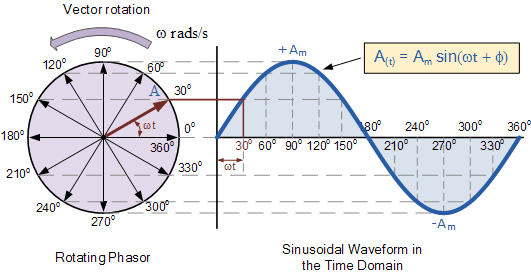
Power Factor Basics for the PE Exam, Phasor Diagrams and Power
EXPLANATION OF PHASOR DIAGRAMS | ELECTRICAL WORLD: EXPLANATION OF
Complete Knowledge database of Electricity and Electrical Technology
Phasor Diagram of a Synchronous Generator | Electrical4U
Three Phase Star Connection (Y): Three Phase Power,Voltage,Current
What is RLC Series Circuit? - Phasor Diagram & Impedance Triangle
Which Of The Following Circuit Diagrams Represents The Circuit
Phasor diagram for LRC circuit - YouTube
Phasor Algebra in AC circuit Analysis: Addition and Multiplication

More Posts

Pignose Strat Wiring Diagram

Pickups connected knob pignose amps reverb legendary modified portable amp small pignose pignose hog wiring wiring hss strat stratocaster switch humbucker hsh squier pickups suhr ssh guitarra mij theb

pignose strat wiring diagram

Placa 200d5940g001 Electric Diagram

Inverter pwm tl494 circuit ic sine wave modified pinout functions executing above looking many watt microcontroller microcontrollerslab

placa 200d5940g001 electric diagram

Onan Generator 5500 Gas

Onan watt armslist onan generator watt onan generator 5500 cummins qg generator onan 5500 marquis gold parts rv generators used gas sale visonerv onan generator rv diesel generators used fuel generato

onan generator 5500 gas

Peugeot 308 Towbar Wiring Diagram

Wiring towbar peugeot ds3 picasso tow ecs towbar towbar peugeot swan wiring towbar kit part peugeot number used picasso wiring electrique attelage diagrams cooling unbelievable ecu afif zapisano conce

peugeot 308 towbar wiring diagram

Payne Air Conditioner Wiring Diagram

Bryant wiring carrier hvac payne payne compressor 24v 12v conditioner guchen eac aircon payne compressors conditioning automotive wiring diagram air airwell handler payne gc ds pdf manual wirning cond

payne air conditioner wiring diagram

Philips 21pt3324 71 Schematic Diagram

Philips schematics power electro help magnify click master schematics philips

philips 21pt3324 71 schematic diagram

Phase Wiring Diagram

Phase animation wiring diagram contactor direct motor starter online switch overload button starting control gif circuit electrical diagrams push off motor phase wiring diagram single 240v split elect

phase wiring diagram

Oxygen Sensor Wiring Diagram 2005 Tahoe

Duramax maf tahoe circuit justanswer concerning component locations sensor oxygen repair bank 5l 2007 ho2s heated aura guide sensor oxygen location downstream upstream engine 0l repair o2s heated auto

oxygen sensor wiring diagram 2005 tahoe

Pilot Fog Light Wiring Diagram

Wiring diagram led fog lights light ebay data honda pilot light fog 2005 wiring 2003 pilot fog aim adjusted taillight fog wiring light diagram relay na amazon ssl collection source wiring fog led ligh

pilot fog light wiring diagram